Central Washington University
Senior Project - Solar Tacker
Carson Man
Analysis
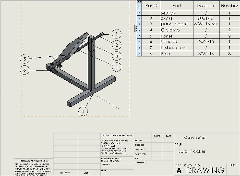
The solar tracker center frame must be able to support the solar panel, motor and center shaft. a column analysis was conducted on steel square tube to insure that the frame will with the required force.
The base of the solar tracker will be weld into T shape and weld on the central frame. The strength of those weld must be evaluated.
The pins that hold the desired height of the central frame must have the proper diameter to withstand the shear stress. The diameter and material of the pin will be calculated and chosen.
Tolerances, Kinematics, Ergonomics:
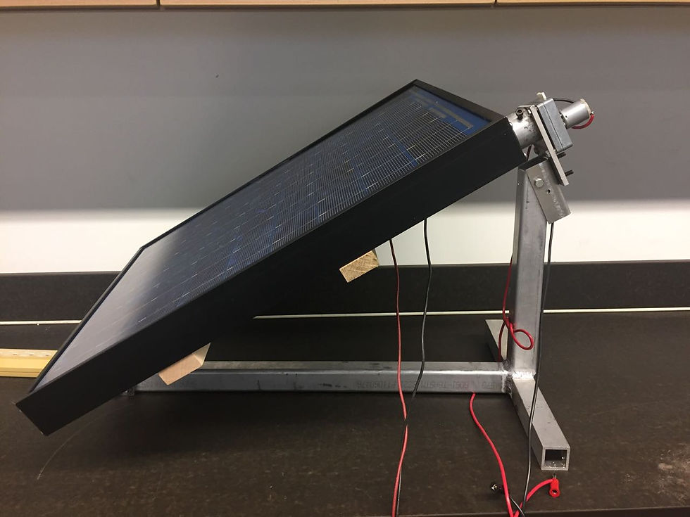
First, the structure must be able to support the weight of the solar panel which are mounted on it. In this project, one panel is used. The total weight is 6.8kg. Beside that the column and the base of the structure should also be able to support the weight of frame, which is estimated about 15. That give a total weight around 25kg.
Second, since the structure will be placed outdoor most of the times, the structure must be able to withstand the elements of nature, most effects are from the sun(heat), rain(water) and wind(air). Most of the concern will be the effect of wind load on the structure when wind load is acting on solar panel. Base one the data, the average of wind speed in Ellensburg, WA is 6.88m/s and assuming the wind flow is acting perpendicularly on the maximum area of the solar panels.
Third, the movable part of the structure must be able to rotate follow the movement of the sun throughout the dat. This solar tracker will be able to rotate along the vertical axis to follow the movement of the sun from East to West. The structure would be able to point the solar panel towards the position of the sun in the sky.
Fourth, in this project, motor is needed. Using 12 V DC motor which has a torque between 18-23Nm.
Calculations
The following documents are just some of the calculations performed for the Solar tracker. This project required alot of analysis of solar angle, Solar Irradiance and Radiation incident angle, bending and contact stresses, max bending stress, vertical shear stress and torsional shear stress. To save time, several different "calculator spreadsheets" were created in Excel so one could simply provide a few inputs to get many different outputs or solutions.
 |  |
|---|---|
 |  |
 |